Phase Locking in PRPD Pattern Recording
-
10 October 2019
-
Brad Monaghan
Following a previous article on PD phase plots, this article explains the importance of achieving a phase lock while capturing phase resolved partial discharge (PRPD) patterns.
What is a phase lock?
A phase lock is applied while recording PRPD patterns to ensure data quality.
It effectively matches the frequency of your test instrument to the typical 50/60Hz frequency of the HV network, whilst conducting PD tests.
As PD occurs, it will generate discharges or events that can be captured and plotted along one cycle of a 50/60Hz sine wave, creating a pattern which can be interpreted.
This will provide the end user of the test equipment with a clear and accurate PRPD pattern that can be analysed on-site, off-site and compared to historical data for condition monitoring purposes. A properly phase locked PRPD pattern will assist in the classification of potential partial discharge activity.
An example:
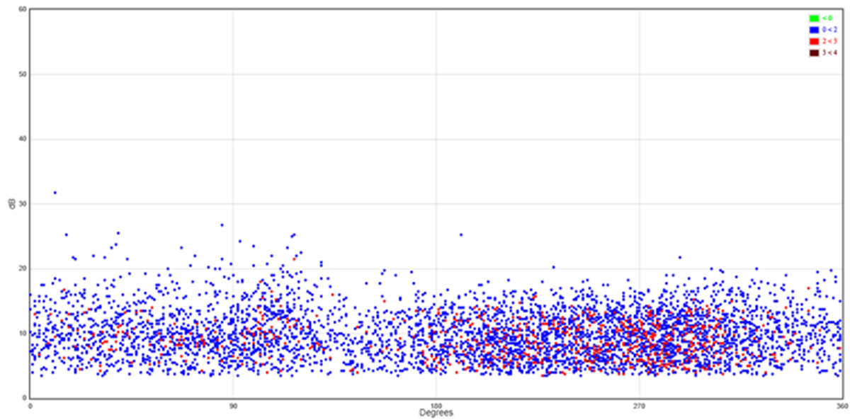
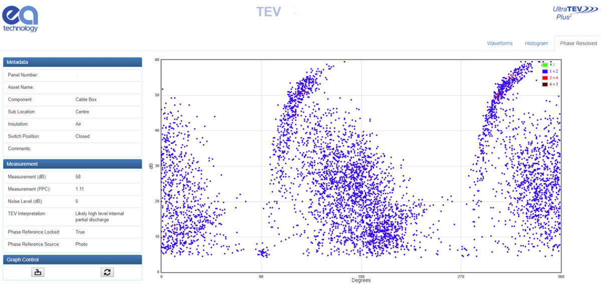
Below are two separate PRPD patterns using the TEV technique, recorded from the same location on an 11kV pitch filled cable box inside a switch room. There is an internal void type PD defect discharging at the time of test within the pitch filled cable box.
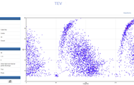
Test 1: The below screenshot displays a PRPD pattern which was not properly phase locked. The instrument was not recording data at the same frequency as the system frequency during the 10 second test. By analysing this pattern, it is difficult to say with certainty that PD activity has been detected.
Test 2: The data below was recorded shortly after in the same location but this time, a successful phase lock ensured the instrument was locked onto the system frequency. The below PRPD pattern indicates an internal void type discharge is occurring inside the 11kV pitch filled cable box – with very high certainty.
How do I achieve a phase lock?
Using EA Technology’s UltraTEV Plus², a phase lock can be achieved three different ways:
- Photo sensor – A photo sensor on the front of the instrument will lock on to nearby mains frequency lighting such as a fluorescent fitting when there is a line of sight between the sensor and the light.
- E-Field – An internal sensor will detect and lock on to the stray electric fields within the substation.
- Manual – Allows the user to manually adjust the phase reference.
Does the 50/60Hz frequency change that much?
System frequency on most electrical networks will tend to slow down and speed up away from its intended setting of usually 50/60Hz, all day every day.
Power generation companies and network operators make their best efforts to keep the system frequency at the intended 50/60Hz to maintain a high quality of supply but due to a range of factors, the frequency will inherently drift.
This drift is enough to affect the PRPD pattern recordings of test equipment such as the UltraTEVPlus² because each TEV, Ultrasonic and Cable PD recording captures 10 seconds of data – enough time for drift in the power system. The instrument is accurate to 0.01Hz.
Conclusion:
Data quality is a large component in the diagnosis and condition monitoring process. Accurately phase locked PRPD patterns allow for better decision making and more effective use of time for all staff involved.
Read out previous article on PD phase plots.