Case Study: How EA Technology Predicted Cable Failure 4 Years in Advance
-
21 September 2020
-
Neil Davies
The Customer
An Australian natural gas-fired power station
Background
In June 2016, a customer of EA Technology was utilising their CableData Collector instrument to assess the insulation condition of their 6.6kV cable systems.
A total of 20 HV cables were tested over three separate testing days. One cable was emitting cable PD signals. These signals were remotely analysed by EA Technology where a source of PD was confirmed to be emanating
from a known transition joint along the cable route.
Around four years later in July 2020, the HV cable XLPE/PILC transition joint failed at the location determined within the test report: approximately 440m along the 640m long cable run.
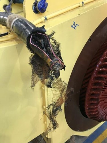
Below is a photo of the joint after failure: Failed 6.6kV Transition joint, XLPE to PILC
Actions
The following conclusions and recommendations were from EA Technology’s test report:
Conclusion: A source of partial discharge was detected on the 6.6kV Cable at around 68-70% of the length of the circuit. There is an XLPE/PILC transition joint at the 65% position and this is therefore the likely source of the PD
activity.
Recommendation: It is recommended to replace the HV cable joint if this asset runs a high risk to the plant. Prepare for a failure of the joint.
Decision: The client chose to leave the discharging defect in service as they were prepared with appropriate spare equipment for any failure that may occur and the location of the transition joint posed minimal safety risk to workers onsite due to its physical location.
The System
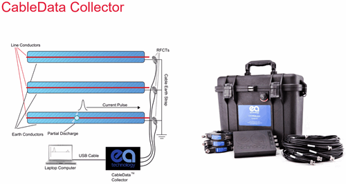
The CableData Collector™ identifies and allows you to report on PD activity in LIVE MV/HV cable networks. This early identification helps to reduce the need for disruptive maintenance outages, by highlighting high risk areas in ample time for repairs and replacements to be made.
Cable PD data can be captured online, without shutting down the HV asset, by placing a split core HFCT (High Frequency Current Transformer) around the earthed screen wires at the ends of HV cables under test. Single
or three phase measurements can be captured.
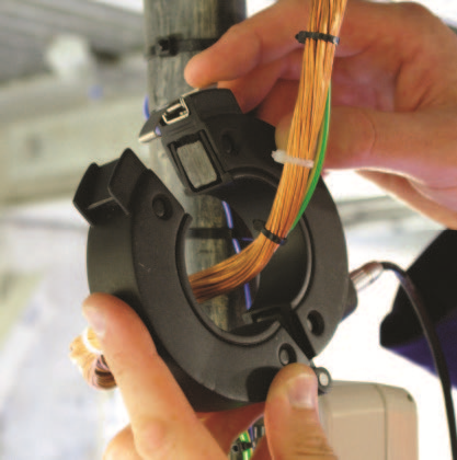
An example of the split core HFCT being used in the field is shown below. Split core HFCT applied to HV cable earthed screen wires:
Test details are entered into a laptop PC and the CableData Collector is set to record cable PD signals.
This particular data capture took 1 minute and 9 seconds. Most data captures take anywhere from 1—10 minutes once the test equipment is set up and recording.
EA Technology software, CableData Analysis Suite, is then employed offsite to ascertain PRPD pattern, conduct waveform analysis and calculate distance to the origin of PD signals along the HV cable under test.
Below is the cable PD data captured from the 6.6kV cable which failed in the pre-determined location four years later:
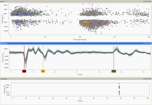
PRPD Pattern, Waveform Analysis and PD Location traces.
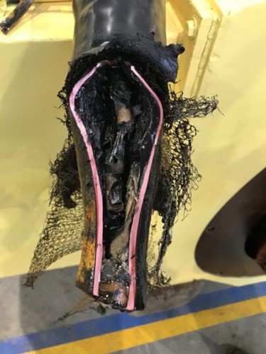
The failed transition joint.
Conclusions
This case study proves the accuracy of PD detection and the value of having the right information to prepare for future failure and make informed decisions.
The CableData Collector test instrument enables HV network operators to test for cable PD while the cable is energised — access to the HV earth screens is required. Testing can be done at any stage throughout the cable’s
life.