The World of Transformer DGA and Thermal Faults
-
29 August 2023
-
Jonathan Lewin
The world of Dissolved Gas Analysis (DGA) is a complex place and although we cannot cover everything in this blog, we will try and provide you with a basic understanding.
Why carry out DGA on oil samples?
DGA is the only way to understand the operational condition of any oil filled electrical asset. When an asset suffers a thermal fault such as Partial Discharge, Heating or Arcing activity the fault generation releases gases which are dissolved and held within the oil sample. By taking regular (annual) oil samples these markers can be assessed, quantified and monitored so action can be taken before the thermal fault results in a catastrophic failure of the asset. This is what we are trying to prevent.
Preventing such failures can save tens or even hundreds of thousands of pounds on costly asset replacement, not to mention the down time of networks and facilities caused by the power outage!
How do we do it?
All oil laboratories should and will be carrying out DGA in accordance with the testing standard IEC 60567: Oil-filled electrical equipment – Sampling of gases and analysis of free and dissolved gases – Guidance (or the equivalent ASTM methodology). The IEC 60567 standard outlines the process to be used for the extraction and analysis of the dissolved gases held within the oil.
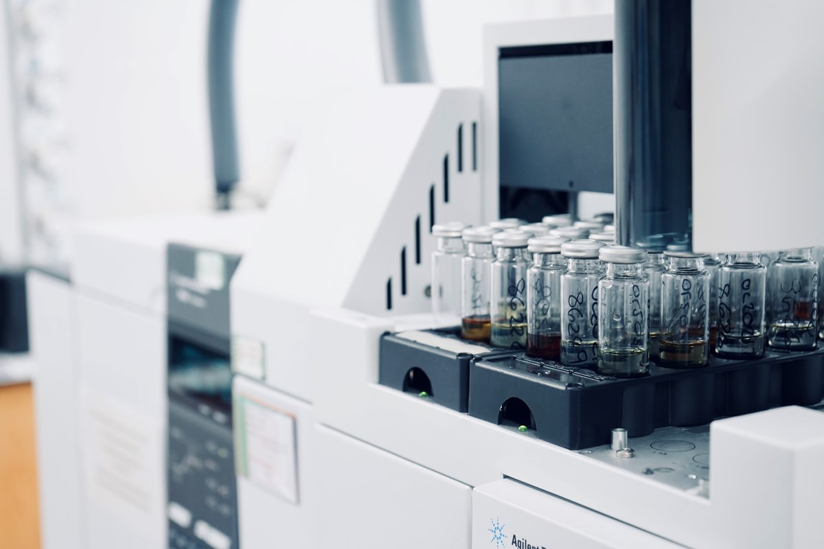
The most widely and accepted method of gas extraction is via headspace extraction which heats the oil sample and releases the gases from the oil into the headspace of a vial, the headspace is then extracted and sent through the Gas Chromatograph (GC) for analysis / detection.
However, there is another option when it comes to DGA and gas extraction and that is to use total gas extraction. This method removes ALL the gases from the oil in multiple extractions and sends them through the GC for analysis / detection. The total method is reportedly a more accurate method as it removes all of the gases from the oil. This method is also supported by the IEC 60567 standard but as stated the headspace method is the industry norm at present.
Thermal faults and gas generation
Now that the analysis has been completed and the chromatographs reviewed by the chemists, we have a quantification of all the gases within the sample in ppm (parts per million). Although the DGA assesses nine main gases the most important gases to be aware of are as follows:
- Hydrogen – Generated by Partial Discharge activity. Also produced by an arcing fault in equal quantities as the Acetylene gas.
- Methane – Low temperature thermal heating gas, generally below 300°C.
- Ethane – Medium temperature thermal heating gas, generally between 300°C - 700°C.
- Ethylene – High temperature thermal heating gas, generally above 700°C.
- Acetylene – Gas generated by an arcing fault (Electrical Discharge).
As a basic rule the higher each gas, the more severe the fault is and the more stringent the retest of the sample will be. It is important to understand at this point that it is not all about the level of the gas on that sample, to get a full picture of the thermal fault activity multiple samples are needed to determine if the gases are stable, reducing or increasing and it is the rate of change that you should be looking out for.
For example, if we have a transformer with an Ethylene level of 105ppm that was stable around that level with no gas increase then that would need monitoring but would not be of imminent concern. If we had an asset that had an Ethylene level of 50ppm that increased to 90ppm then that could signify an active / developing fault and would give rise for concern. So it is more than just looking at the individual result and regular analysis gives you a much more detailed account of the activity within an asset.
Interpretation
There are several interpretation techniques available for use when it comes to DGA and they all have their positives and negatives, the place to start if you want detailed information and guidance is standard IEC 60599: Mineral oil-filled electrical equipment in service. Guidance on the interpretation of dissolved and free gases analysis and the IEEE C57.104 Guide for the Interpretation of Gases Generated in Oil-Immersed Transformers. The IEEE guidance document details the Key Gas Method which is widely used in industry and forms a good base for most interpretation. The IEC 60599 document covers interpretation information such as Rogers Ratio, Duvals Triangle and CO/CO2 gas ratio.
Both documents are useful and provide critical interpretation information regarding DGA and oil analysis, any good laboratory will use these as a reference document and can provide a breadth of interpretation on the DGA results but also carry out interpretation and guidance based on the individual asset and history of each asset. It is important to understand the assets, their operation, history and get a good feel for how they have been managed and what is normal for them to get the most out of any interpretation of DGA.
So, there you have it…although the above is only a high-level brief on DGA there is much more detailed information out there and if you want to know more feel free to get in touch, but for now I hope this has been a useful insight into the world of DGA.
You can find out more about EA Technology's oil analysis service here.
Join us in our next blog where we look at How Wet is the Oil……Or is that how Wet is the Transformer?
