Infrared Thermography vs Partial Discharge Testing
-
02 January 2022
-
Jorge Rivera
Let’s compare tools for outdoor medium and high voltage online electrical inspections: IR Thermography, Ultrasonic (Acoustic), UHF (RF). One is a poor choice for partial discharge testing. In this FAQ, we’ll compare the technologies plus offer some best practices and selection advice.
Substation and other MV/HV electrical asset failure can be devastating. Apart from creating outages, halting production, and other day-to-day activity, necessitating crisis management, it could cause a reportable health and safety incident. In a worst-case scenario, the outcome could even be injury or fatality.
These technologies do have some obvious common benefits as part of a predictive maintenance program:
-Online testing (test while equipment and cables are energized)
-Non-contact testing
-Non-destructive testing (NDT)
-Quicker and less expensive than offline tests
-Useful to screen for further visual inspection and offline tests
Thermal Camera is not recommended for Partial Discharge inspections
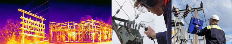
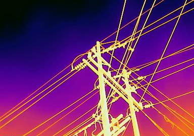
Thermal cameras look at infrared energy emitted from target objects. What this means for electrical inspections is we’re looking for overheated electrical assets. For example, loose and corroded connections creating higher resistance leading to higher temperatures, or unbalanced loads with temperature differences between phases, or a lower liquid level due to a transformer oil leak will be evident with proper use of thermography.
Partial discharge, however, is a problem for thermal cameras. Thermography depends on current with the power proportional to the square of the current times resistance (higher current leads to higher temperatures and also higher resistances lead to higher temperatures). Partial discharge causes insulation to overheat and repeated occurrence has a cumulative effect that can lead to damage and ultimate failure. However, it is very short distance and fast (a few nanoseconds duration every few milliseconds interval), so only in severe extreme advanced cases, such as in an advanced arcing, would there be a chance for the heat to be picked up by a thermal camera, even a high-quality model. Internal partial discharge (i.e. inside an insulator) would be extremely unlikely to ever be picked up.
Insulation degrades with age. Additional factors can lead to premature failure, such as moisture, dirt/contamination, poor workmanship, and/or defective materials. At the point of degradation, the insulation failure occurs when it is unable to withstand the electric field applied to it and a fault occurs. This is a voltage event. For an extreme example, consider a standby medium voltage cable with surface partial discharge that is energized, but has effectively no load, will still emit ultrasonic and UHF by-products.
In short, IR testing and PD testing methods are complementary techniques to detect different types of electrical failures.
Types of Partial Discharge
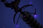 Credit: Wikipedia Corona Discharge
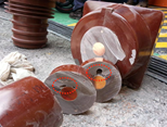
Online Partial Discharge Detection Methods
We say online because these methods are performed while equipment and cables are energized at line voltages. Offline methods would disconnect and remove the equipment and cable from service for testing. While online PD testing is not able to vary the voltages as is possible offline, it has advantages of being performed without an outage, quicker to perform, uses less expensive instruments, and does not require such a high level of expertise.
Ultrasonic (Acoustic) Method. Usually, acoustic emissions produced by PD are ultrasonic, meaning that their frequency is too high for the human ear, therefore an instrument is required to convert this into the audible range. As the PD gets worse, the frequency sometimes decreases into the audible range. An airborne ultrasonic microphone is the most sensitive way to detect PD where there is an air path between the source and the microphone: a line of sound. For sealed chambers, contact ultrasonic sensors can be used. Ultrasonic methods are particularly effective at finding surface PD and corona PD.
Transient Earth Voltage (TEV) Method. Different types of PD can be easily identified through a combination of sensors. PD generates high-frequency electromagnetic pulses known as Transient Earth Voltages (TEV). These TEV signals move across the inside surfaces of switchgear, finding their ways to the equipment’s exterior through any gaps in the metalwork looking for a path to ground. A TEV sensor on the outside of the switchgear can measure these pulses, and is particularly effective for detecting internal PD. EA Technology’s Dr John Reeves discovered the phenomenon in the early ‘80’s, gave it the TEV name used to this day, and pioneered the development of instruments made by EA Technology and others around the world.
Electromagnetic Field (EMF) / Radio Frequency Interference (RFI) Method. RFI due to PD is broadband in nature and can be detected across a range of frequencies. Lower frequencies tend to radiate further from a source than higher frequency so it follows that detection at higher frequencies will allow a more precise location of a source. These radio waves can generate TEVs on the surrounding metalwork. Surface and internal PD can be detected. Permanent UHF antennas or portable directional antennas can be used. UHF is preferred over VHF for several reasons:
-UHF has a shorter antenna which is better in open terminal switchyards (antenna length is related to radio wave length).
- Cross coupling and propagation of signals from other assets is reduced.
- UHF signal attenuates quickly from the source so with an instrument capable of variable gain function localization is possible.
- Non-destructive corona PD can produce a lot of noise particularly on high humidity and damp days. PD frequency components for corona into air decay rapidly above 250MHz, so measuring in UHF frequencies will effectively ignore harmless corona.
- Metal-cladding will act as a Faraday cage, while making UHF less effective from outside, becomes an advantage for permanent internal sensors.
High-Frequency Current Transformer (HFCT. Also called RFCT for radio frequency) Method. When installed around the earth connection or strap between the cable sheath and the earthed switchgear, it allows the high frequency current transients that are generated by PD activity within the cable, cable joints or local switchgear to be detected.
Thermal Camera Selection and Best Practices for Outdoor Electrical Inspections
There is a large variety of thermal cameras and PD test equipment price points and specifications to consider for selection. Having a great instrument depends on proper use as well. This section and the next will discuss selection and best practices for outdoor electrical inspections. Always respect safety clearances.
Just because the crosshair is on a target does not mean the thermal camera is looking at just that target. Picture in your mind a flashlight pointed close to a wall. The cone of light has a small diameter that will grow as one moves back from the wall. A thermal camera has thousands of detector elements determined by the resolution (i.e. pixels). At a given distance, if the pixel size is 1 inch, then a 1/2 inch target will have surrounding temperature averaged into the measurement, leading to a lower reading. The best way to avoid this is to get closer to the target or use a thermal camera with better resolution and/or an optical telephoto lens. Thermal drones are an option many choose but not required. Just to look at real numbers see the table below.
IFOV is the instantaneous field of view, i.e. pixel spot size in inches. A typical utility pole is 35 ft. Using the Pythagorean theorem looking at a target at the top from a 45 degree angle at ground 35 feet horizontally and vertically would be roughly 50 ft hypotenuse distance for the thermal camera. Similarly, an EHV transmission tower of typical 120 ft height would be 170 ft distance. Looking at the first row of the table at 50 feet, the target must be smaller than 0.55 inches to avoid averaging in surrounding temperatures and at 170 feet it would be 1.87 inches. The second row is the same model with a telephoto lens which decreases the IFOV. The 3rd and 4th rows are a different model with lower resolution with standard and telephoto lenses for comparison. In short, higher resolution and use of a telephoto lens, provide better IFOV’s. Accuracy is mentioned in the table only as a reminder that high accuracy is helpful but not necessary. Repeatability between tests and Comparisons are more important. Look for unbalanced loads or loose/corroded connections with higher temperatures, as compared to others in the same frame or at least same condition (time of day, cloud cover, wind, ambient temperature, and humidity). Thermal sensitivity is typically expressed in milli Kelvin (mK). It is a measure of how well the thermal camera can resolve two different temperatures. The lower the number, the better the model. |
An overheated component might have more of a temperature differential in the early morning or evening by avoiding mid-day sun.
Test during peak load times, such as summer A/C season, is better.
Remember to adjust emissivity as it will vary by material: porcelain vs copper vs painted metal.
Don’t point a thermal camera at an outdoor electrical asset with the sun directly behind. It may damage the detector element.
Make sure the target of interest is in focus. Focus problems can’t be fixed in the PC software later. Lower cost fixed focus cameras are not recommended for the distances involved with utility poles and taller EHV power lines.
Best Practices for Outdoor Partial Discharge Electrical Inspections
For surface PD, corona, or sparks jumping a gap in outdoor equipment, there is nothing better than a parabolic ultrasonic dish (at EA Technology we call ours UltraDish).
When using the UltraDish for outdoor assets, scan overhead lines, insulators, transformer bushings, terminations, connection points, etc. for the largest signal.
For internal void, perform TEV testing on cable ground straps, struts, and outside of MV/HV cables. TEV testing on anything conductive will detect the signals but pinpointing them is where the UHF comes in as it is able to point-and-shoot at the internal void defect.
UHF will see both surface and internal void, so it is used in conjunction with the TEV and UltraDish. Use UHF for any exposed MV/HV asset. UHF will see internal void if the UHF signals can escape the asset through gaskets/UHF paths – similar to the way TEV comes out. UHF is also used from outside the safety zone, fence-line, or underground cable pits, as a safety check prior to entry.
When using our UHF Directional Antenna, the user can detect PD from hundreds of meters away when at a very high gain setting (higher gain = higher sensitivity) and in a UHF quiet environment. The trick is to be able to then triangulate which asset is discharging and discounting other nearby assets. This is performed by lowering the gain (making the antenna less sensitive) and walking toward the asset. Rotate instrument 90 degrees to account for polarization.
The UHF spectrum can be quite crowded, but transmission interference sources tend to be narrowband. It’s important for the instrument to be able to perform a wideband frequency sweep to find a quiet narrowband. Narrowband in our UHF uses a narrow slice of the RF band, centered at the set frequency. Globally 800 MHz tends to be unused, so it is default narrowband for our instrument. For example, in the USA several portions of the 800 MHz spectrum are reserved by the FCC for police and first responders so it should be quiet around a switchyard. Or one can adjust the narrowband focus up or down to find a quiet region based on the wideband review.
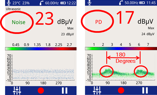
Genuine discharge with ultrasonic or UHF inspections can be identified by a crackling sound (like a sizzling frying pan) in the headphones or by phase related groups on phase plot. The sound will change with varying signals. Listen for a signal with mains frequency content: 50/60 Hz or 100/120 Hz. Further confidence of a detection can be obtained by the PRPD (phase resolved partial discharge) plot and a PD vs Noise classification algorithm.
 |
|
Partial discharge, unlike most other interfering signals, will be phase resolved. This means when graphed there will be groups indicated on the phase resolved screen that are separated by 180 degrees (corona discharge will usually have a single grouping). Noise tends to be out of phase and occurs at irregular positions on the phase plot. It’s important with portable instruments, like with our UltraTEV Plus 2, to display the PRPD plot as PD testing is performed instead of waiting for PC based analysis. This will aid along with the headphones in separating noise from true PD and focus testing efforts in the field. Our UltraTEV Plus 2 additionally has a proprietary classification algorithm to determine noise from PD. The algorithm looks for patterns within the real-time data stream which experts at EA Technology, based on our 40+ years of experience, have identified as typical indicators of partial discharge. For PRPD plots to be drawn correctly, the power frequency must be known to the decimal. For example, 59.98 Hz in a 60 Hz country or 50.02 in a 50 Hz country. Portable instruments make it more difficult but can be done. Our UltraTEV Plus 2 for example has a built-in photo sensor using fluorescent lighting indoors, an E-field sensor for outdoors, and option to enter the value manually. A properly ‘phase referenced’ Phase Plot will assist in the classification of potential partial discharge activity that has been recorded. It will provide a much clearer Phase Plot that can be analyzed and compared to other readings/phase plot patterns. |
Surface PD is temperature and humidity dependent (particularly humidity), so it is important to record these values to aid in comparison of tests over time. High humidity days/times are best for testing. Our portable UltraTEV Plus 2 and fulltime Astute Monitoring include a temperature/relative humidity probe.
Closing thoughts on IR and PD Testing
IR and PD testing are complementary technologies. When used correctly, instead of replacement by age or service life, these technologies can be incorporated into a condition-based monitoring (CBM) approach to identify problems and repair/replace as needed. Test from different positions/angles to ensure the correct target is being observed.
Partial Discharge is the most common cause of disruptive failure of switchgear, with research showing that 85% of disruptive failures in HV and MV equipment are linked to PD damage. Therefore, if there was only time and funds for one type of testing, online PD testing would provide the best ROI for MV & HV electrical assets.
Additional Learning on PD Testing
Webinar: Introduction to Partial Discharge
FAQ Article: Partial Discharge Testing (PD Testing)
Video tutorial: Performing Ultrasonic PD testing with UltraTEV Plus 2
Video tutorial: Performing TEV PD testing with UltraTEV Plus 2
Webinar: Using UHF to Detect PD
FAQ Article: What is a Phase Resolved Partial Discharge (PRPD) plot telling you?

Talk to an Expert
Thank you for your interest in EA Technology. You can request information or a free callback by clicking the link below. One of our experts will be in touch with you shortly.